Rotations - Demo 07
Objective
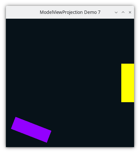
Attempt to rotate the paddles around their center. Learn about rotations. This demo does not work correctly, because of a misunderstanding of how to interpret a sequence of transformations.
Demo 07
How to Execute
Load src/modelviewprojection/demo07.py in Spyder and hit the play button.
Move the Paddles using the Keyboard
Keyboard Input |
Action |
|---|---|
w |
Move Left Paddle Up |
s |
Move Left Paddle Down |
k |
Move Right Paddle Down |
i |
Move Right Paddle Up |
d |
Increase Left Paddle’s Rotation |
a |
Decrease Left Paddle’s Rotation |
l |
Increase Right Paddle’s Rotation |
j |
Decrease Right Paddle’s Rotation |
For another person’s explanation of the trigonometry of rotating in 2D, see
Rotate the Paddles About their Center
Besides translate and scale, the third main operation in computer graphics is to rotate an object.
Rotation Around Origin (0,0)
We can rotate an object around (0,0) by rotating all of the object’s vertices around (0,0).
In high school math, you will have learned about sin, cos, and tangent. Typically the angles are described on the unit circle, where a rotation starts from the positive x axis.

We can expand on this knowledge, allowing us to rotate all vertices, wherever they are, around the origin (0,0), by some angle \(\theta\).
Let’s take any arbitrary point

From high school geometry, remember that we can describe a Cartesian (x,y) point by its length r, and its cosine and sine of its angle \(\theta\).

Also remember that when calculating sine and cosine, because right triangles are proportional, that sine and cosine are preserved for a right triangle, even if the length sides are scaled up or down.
So we’ll make a right triangle on the unit circle, but we will remember the length of (x,y), which we’ll call “r”, and we’ll call the angle of (x,y) to be “\(\beta\)”. As a reminder, we want to rotate by a different angle, called “\(\theta\)”.

Before we can rotate by “\(\theta\)”, first we need to be able to rotate by 90 degrees, or \(\pi\)/2. So to rotate (cos(\(\beta\)), sin(\(\beta\))) by \(\pi\)/2, we get (cos(\(\beta\) + \(\pi\)/2), sin(\(\beta\) + \(\pi\)/2)).

Now let’s give each of those vertices new names, x’ and y’, for the purpose of ignoring details for now that we’ll return to later, just let we did for length “r” above.

Now forget about “\(\beta\)”, and remember that our goal is to rotate by angle “\(\theta\)”. Look at the picture below, while turning your head slightly to the left. x’ and y’ look just like our normal Cartesian plane and unit circle, combined with the “\(\theta\)”; it looks like what we already know from high school geometry.

So with this new frame of reference, we can rotate x’ by “\(\theta\)”, and draw a right triangle on the unit circle using this new frame of reference.

So the rotated point can be constructed by the following

Now that we’ve found the direction on the unit circle, we remember to make it length “r”.

Ok, we are now going to stop thinking about geometry, and we will only be thinking about algebra. Please don’t try to look at the formula and try to draw any diagrams.
Ok, now it is time to remember what the values that x’ and y’ are defined as.
A problem we have now is how to calculate cosine and sine of \(\beta\) + \(\pi\)/2, because we haven’t actually calculated \(\beta\); we’ve calculated sine and cosine of \(\beta\) by dividing the x value by the magnitude of the a, and the sine of \(\beta\) by dividing the y value by the magnitude of a.
We could try to take the inverse sine or inverse cosine of theta, but there is no need given properties of trigonometry.
Therefore
58@dataclasses.dataclass
59class Vector2D(mu1d.Vector1D):
60    y: float  #: The y-component of the 2D Vector
 82def rotate_90_degrees() -> mu.InvertibleFunction:
 83    def f(vector: mu.Vector) -> mu.Vector:
 84        assert isinstance(vector, Vector2D)
 85        return Vector2D(-vector.y, vector.x)
 86
 87    def f_inv(vector: mu.Vector) -> mu.Vector:
 88        return -f(vector)
 89
 90    return mu.InvertibleFunction(f, f_inv)
 91
 92
 93def rotate(angle_in_radians: float) -> mu.InvertibleFunction:
 94    r90: mu.InvertibleFunction = rotate_90_degrees()
 95
 96    def create_rotate_function(
 97        perp: mu.InvertibleFunction,
 98    ) -> typing.Callable[[mu.Vector], mu.Vector]:
 99        def f(vector: mu.Vector) -> mu.Vector:
100            parallel: mu.Vector = math.cos(angle_in_radians) * vector
101            perpendicular: mu.Vector = math.sin(angle_in_radians) * perp(vector)
102            return parallel + perpendicular
103
104        return f
105
106    return mu.InvertibleFunction(
107        create_rotate_function(r90),
108        create_rotate_function(mu.inverse(r90)),
109    )
Note the definition of rotate, from the description above. cos and sin are defined in the math module.
85@dataclasses.dataclass
86class Paddle:
87    vertices: list[mu2d.Vector2D]
88    color: colorutils.Color3
89    position: mu2d.Vector2D
90    rotation: float = 0.0
a rotation instance variable is defined, with a default value of 0
118def handle_movement_of_paddles() -> None:
119    global paddle1, paddle2
120
121    if glfw.get_key(window, glfw.KEY_S) == glfw.PRESS:
122        paddle1.position.y -= 1.0
123    if glfw.get_key(window, glfw.KEY_W) == glfw.PRESS:
124        paddle1.position.y += 1.0
125    if glfw.get_key(window, glfw.KEY_K) == glfw.PRESS:
126        paddle2.position.y -= 1.0
127    if glfw.get_key(window, glfw.KEY_I) == glfw.PRESS:
128        paddle2.position.y += 1.0
129
130    if glfw.get_key(window, glfw.KEY_A) == glfw.PRESS:
131        paddle1.rotation += 0.1
132    if glfw.get_key(window, glfw.KEY_D) == glfw.PRESS:
133        paddle1.rotation -= 0.1
134    if glfw.get_key(window, glfw.KEY_J) == glfw.PRESS:
135        paddle2.rotation += 0.1
136    if glfw.get_key(window, glfw.KEY_L) == glfw.PRESS:
137        paddle2.rotation -= 0.1
Cayley Graph
Code
The Event Loop
146while not glfw.window_should_close(window):
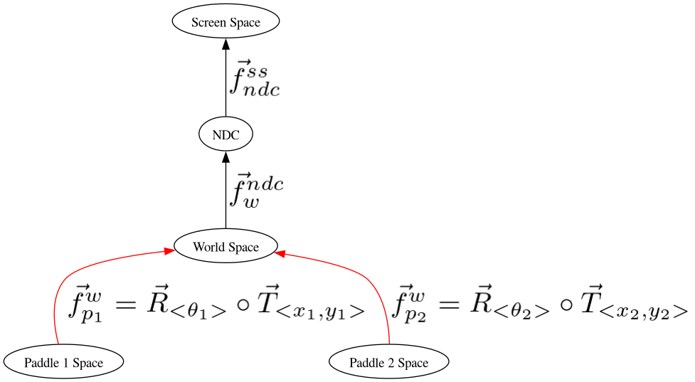
So to rotate paddle 1 about its center, we should translate to its position, and then rotate around the paddle’s center.
165    GL.glColor3f(*iter(paddle1.color))
166
167    GL.glBegin(GL.GL_QUADS)
168    for p1_v_ms in paddle1.vertices:
169        # doc-region-begin compose transformations on paddle 1
170        fn: mu2d.InvertibleFunction = mu2d.compose(
171            [
172                mu2d.uniform_scale(1.0 / 10.0),
173                mu2d.rotate(paddle1.rotation),
174                mu2d.translate(paddle1.position),
175            ]
176        )
177        paddle1_vector_ndc: mu2d.Vector2D = fn(p1_v_ms)
178        # doc-region-end compose transformations on paddle 1
179        GL.glVertex2f(paddle1_vector_ndc.x, paddle1_vector_ndc.y)
180    GL.glEnd()
...
Likewise, to rotate paddle 2 about its center, we should translate to its position, and then rotate around the paddle’s center.
184    GL.glColor3f(*iter(paddle2.color))
185
186    GL.glBegin(GL.GL_QUADS)
187    for p2_v_ms in paddle2.vertices:
188        fn: mu2d.InvertibleFunction = mu2d.compose(
189            [
190                mu2d.uniform_scale(1.0 / 10.0),
191                mu2d.rotate(paddle2.rotation),
192                mu2d.translate(paddle2.position),
193            ]
194        )
195        paddle2_vector_ndc: mu2d.Vector2D = fn(p2_v_ms)
196        GL.glVertex2f(paddle2_vector_ndc.x, paddle2_vector_ndc.y)
197    GL.glEnd()
Why it is Wrong
Turns out, our program doesn’t work as predicted, even though translate, scale, and rotate are all defined correctly. The paddles are not rotating around their center.
Let’s take a look in detail about what our paddle-space to world space transformations are doing.
170        fn: mu2d.InvertibleFunction = mu2d.compose(
171            [
172                mu2d.uniform_scale(1.0 / 10.0),
173                mu2d.rotate(paddle1.rotation),
174                mu2d.translate(paddle1.position),
175            ]
176        )
177        paddle1_vector_ndc: mu2d.Vector2D = fn(p1_v_ms)
See modelviewprojection.mathutils.compose
modelspace vertices

Translate

Reset the coordinate system

Modelspace
Rotate around World Spaces’s origin

Modelspace
Reset the coordinate system

Modelspace
Final world space coordinates

Modelspace
So then what the heck are we supposed to do in order to rotate around an object’s center? The next section provides a solution.